 English
 中文简体

Description: 79.5×62×7.3mm copper-based brake pad with 4-hole design. Density 6.2g/cm³, weight 195g. Free from graphite segregation, cracks, and defects. Ideal for heavy-duty industrial braking system...
See DetailsE-mail us: [email protected]
Tel: +86-15239857375


 Home / Author / Tan Xinyue — After-Sales Technical Coordinator / High-Density Copper-Based Brake Pads for Heavy-Duty Industrial Braking
High-Density Copper-Based Brake Pads for Heavy-Duty Industrial Braking
 2026.09.22
 Tan Xinyue — After-Sales Technical Coordinator
Content
- 1 Product Overview and Core Specification
- 2 Why Copper-Based Sintered Friction Material Is Used
- 3 High Density as a Functional Performance Requirement
- 4 Graphite Distribution and Defect Prevention
- 5 Four-Hole Mounting Design and Mechanical Stability
- 6 Dimensional Accuracy and Fitment Control
- 7 Thermal Performance in Continuous and Emergency Braking
- 8 Comparison with Conventional Friction Materials
- 9 Manufacturing Process and Quality Assurance
- 10 Advantages of the Manufacturing Partner
- 11 Application Scenarios
- 12 Installation and Service Recommendations
- 13 Q&A: Common Questions About the Copper-Based Brake Pad
- 13.1 Q1: What is the main advantage of a copper-based sintered brake pad?
- 13.2 Q2: What does the 6.2 g/cm³ density mean?
- 13.3 Q3: Why is graphite segregation a concern?
- 13.4 Q4: What is the purpose of the four-hole design?
- 13.5 Q5: Can the dimensions be customized?
- 13.6 Q6: Is the 79.5 × 62 × 7.3 mm size suitable for every industrial brake?
- 13.7 Q7: Can the pad operate in wet or outdoor conditions?
- 13.8 Q8: What inspections are performed before shipment?
- 13.9 Q9: How should customers select between copper-based and iron-based sintered pads?
- 13.10 Q10: What information is needed for a customized quotation?
- 13.11 Q11: Can samples be supplied for testing?
- 13.12 Q12: How long can the brake pad last?
- 14 Recommended Customer Specification Checklist
- 15 Conclusion
- 16 References
- 17 Product: High-Density Copper-Based Brake Pad | 79.5×62×7.3mm | 4-Hole Industrial Brake Lining

Industrial braking systems operate under demanding conditions that conventional friction materials cannot always withstand. Cranes, mining machinery, wind turbines, rolling mills, conveyors, elevators, marine equipment, and heavy engineering machines may require repeated braking, high clamping pressure, rapid heat dissipation, and reliable performance in dusty, wet, or temperature-variable environments. In these applications, the brake pad is not simply a replaceable wear component. It is a precision-engineered safety element that directly influences stopping distance, equipment availability, rotor life, maintenance cost, and operator safety.
The high-density copper-based brake pad described in this article is a sintered friction material developed for heavy-duty industrial brake assemblies. Its nominal dimensions are 79.5 × 62 × 7.3 mm, with a four-hole mounting configuration, a target density of 6.2 g/cm³, and an approximate weight of 195 g. The material is designed to provide stable friction, strong thermal conductivity, structural integrity, and controlled wear under severe operating conditions.
As a powder metallurgy product, the brake pad is manufactured by blending carefully selected metallic and non-metallic powders, compacting the mixture in a precision die, and sintering the compact under a controlled atmosphere. This process makes it possible to control density, porosity, friction behavior, dimensional accuracy, and material uniformity more precisely than many conventional molded friction-material processes.
A major quality objective is the elimination of graphite segregation, cracks, and other internal or surface defects. Uniform graphite distribution is particularly important because graphite acts as a solid lubricant and contributes to the formation of a stable transfer film on the mating rotor. When graphite is unevenly dispersed, different areas of the same pad may exhibit different friction levels, wear rates, and temperatures. The result can be vibration, uneven wear, rotor scoring, or reduced braking consistency.
The product is intended for industrial applications where reliable friction performance, long service life, low maintenance, and resistance to thermal degradation are more important than the lowest initial purchase price. Its copper-based matrix provides high thermal conductivity, while the controlled powder metallurgy structure supports mechanical strength and dimensional stability.
Product Overview and Core Specification
The brake pad uses a copper-based sintered friction formulation. Copper provides an efficient thermal pathway, helping move heat away from the friction interface and into the backing structure and surrounding brake assembly. This characteristic is valuable in applications involving frequent stops, emergency braking, high rotational energy, or prolonged frictional sliding.
| Parameter | Nominal Specification | Functional Significance |
|---|---|---|
| Material type | Copper-based sintered friction material | Combines thermal conductivity, mechanical strength, and stable friction behavior |
| Nominal dimensions | 79.5 × 62 × 7.3 mm | Designed for compatible industrial brake assemblies |
| Mounting configuration | Four-hole design | Supports secure retention and balanced load distribution |
| Density | 6.2 g/cm³ | Provides controlled porosity, structural integrity, and wear resistance |
| Approximate weight | 195 g | Useful for handling, assembly planning, and replacement logistics |
| Friction coefficient | Approximately 0.35–0.40 under dry conditions | Supports predictable braking torque in suitable operating conditions |
| Wear rate | ≤1.0 × 10⁻⁴ cm³/J | Helps reduce replacement frequency and maintenance interruptions |
| Shear strength | ≥7 MPa | Improves resistance to tangential forces during braking |
| Working temperature | -40°C to 600°C, application dependent | Supports operation across a broad industrial temperature range |
| Quality requirements | Free from graphite segregation, cracks, and visible defects | Promotes uniform friction performance and reliable service |
Dimensions, hole diameter, hole position, countersink geometry, backing arrangement, friction coefficient, density, and other characteristics can be adjusted for a specific brake assembly when the customer supplies a technical drawing, sample, or complete application specification. The nominal configuration should therefore be verified against the caliper or brake mechanism before mass production.
Some industrial brake systems use a thicker self-supporting pad, while others use a thinner friction lining that is attached to a steel backing plate. The 7.3 mm configuration described here should be treated as the principal product specification. Alternative thicknesses or lining-only geometries can be manufactured when the design, attachment method, and load conditions are clearly defined.
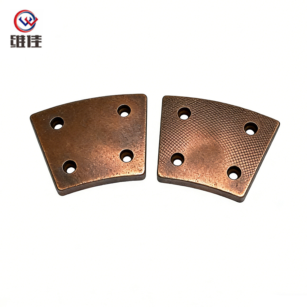
High-Density Copper-Based Brake Pad | 79.5×62×7.3mm | 4-Hole Industrial Brake Lining
Why Copper-Based Sintered Friction Material Is Used
Copper-based sintered friction materials are selected for their combination of heat transfer, load-bearing ability, friction stability, and resistance to repeated thermal cycling. The copper matrix is capable of conducting heat away from the contact area more rapidly than many organic or low-conductivity friction materials. This helps limit local hot spots and reduces the risk of thermal fade during demanding braking cycles.
Thermal fade occurs when the friction coefficient decreases as the pad and rotor become excessively hot. A brake pad that performs well during a single stop may not deliver the same torque after repeated stops if heat accumulates faster than it can be dissipated. In industrial machinery, this problem can be especially serious because the brake may be responsible for holding a suspended load, stopping a moving carriage, controlling a winch, or preventing the uncontrolled movement of a large rotating assembly.
The copper matrix also supports mechanical strength. During powder metallurgy processing, metallic particles form diffusion bonds during sintering. The resulting structure is a consolidated composite rather than a simple pressed powder compact. When density, sintering temperature, time, and atmosphere are properly controlled, the pad can achieve a strong and stable structure while retaining the controlled porosity required for friction performance.
Graphite and other friction modifiers may be incorporated into the formulation to regulate friction, improve lubricity, and promote the formation of a transfer film. The purpose is not to make the surface excessively slippery. Instead, the formulation is engineered to maintain a controlled friction coefficient while limiting direct metal-to-metal contact between the pad and rotor.
Compared with many conventional organic friction materials, copper-based sintered pads are generally better suited to high-temperature and high-load service. They are less dependent on resin stability and can maintain their basic structure during operating conditions that may soften, decompose, or thermally degrade organic binders.
Compared with some iron-based sintered materials, copper-based formulations offer higher thermal conductivity and can be less aggressive toward the mating rotor when properly formulated. They are often a practical choice where rotor service life, stable wet braking, and rapid heat dissipation are important design priorities.
High Density as a Functional Performance Requirement
The target density of 6.2 g/cm³ is not merely a marketing specification. In a sintered friction material, density reflects the degree to which the powder compact has been consolidated and the amount and distribution of residual porosity within the finished component.
A pad with insufficient density may contain excessive or interconnected pores. Such a structure can have reduced mechanical strength, increased compressibility, higher initial wear, and greater sensitivity to fluid or contaminant penetration. Under a high clamping load, an underdense pad may deform more rapidly or develop uneven contact with the rotor.
Controlled porosity is still necessary. A completely dense material is not automatically a better friction material. Some porosity helps accommodate friction modifiers, retain a stable transfer layer, and manage gases or debris generated at the interface. Excessive compaction can isolate graphite particles and reduce their ability to contribute to surface-film formation. The engineering objective is therefore a balanced density with fine, evenly distributed pores rather than maximum density at any cost.
Achieving a consistent 6.2 g/cm³ throughout a production batch requires control at multiple stages. Powder particle size distribution affects die filling and compactability. Powder flowability influences whether every region of the die receives the correct quantity of material. The compaction pressure determines the green density of the pressed part, while ejection conditions influence the risk of cracking or distortion.
Sintering then transforms the compact into a coherent structure. If the temperature is too low or the holding time is insufficient, diffusion bonding may be incomplete. If the temperature is too high, unwanted phase changes, dimensional distortion, lubricant loss, or excessive pore closure may occur. The atmosphere must also be managed to reduce oxidation and support the intended bonding reactions.
Density measurement is therefore useful both as an acceptance test and as a process-control indicator. When density values begin to drift, the cause may be related to powder moisture, particle segregation, die filling, compaction pressure, tool wear, or furnace conditions. Monitoring trends enables corrective action before a large quantity of nonconforming products is produced.
Graphite Distribution and Defect Prevention
Graphite is widely used in copper-based sintered brake materials because of its lubricating behavior and its ability to participate in transfer-film formation. However, graphite has a much lower density than copper. This difference creates a natural tendency for graphite particles to separate or migrate during transportation, mixing, die filling, and vibration.
Graphite segregation can produce significant variations across the working face of a brake pad. A graphite-rich zone may have a lower local friction coefficient and may wear more quickly. A graphite-poor region may operate at a higher temperature and generate greater frictional instability. When these zones occur next to one another, the pad may develop uneven wear, localized heat concentration, vibration, or irregular rotor contact.
Preventing segregation begins with raw-material selection. Particle size, morphology, purity, and surface characteristics all affect the way graphite interacts with copper powder and other additives. A suitable particle-size relationship helps graphite remain distributed throughout the metallic matrix rather than separating during handling.
The mixing sequence is equally important. Metallic powders and reinforcing additives may first be blended to create a consistent base mixture. Graphite can then be introduced under controlled conditions to reduce the risk of floating, clustering, or excessive mechanical damage to the flakes. Mixing time and intensity must be sufficient to achieve uniformity without causing unwanted particle classification.
Process control does not end when mixing is complete. The blended powder should be handled in a way that minimizes vibration and segregation before pressing. Storage containers, transfer distances, feeding equipment, and die-filling procedures can all influence final uniformity.
Cracks are another important defect category. Internal cracks may originate during compaction, especially near corners, holes, sharp geometry transitions, or regions with uneven density. Ejection from the die can also generate tensile stresses if the compact adheres to the tooling or if ejection forces are not balanced.
During sintering, differential thermal expansion between copper, graphite, and other constituents may create additional stress. Heating and cooling rates must be controlled so that the material can accommodate thermal changes without developing internal separation. Tool geometry, lubricant selection, compaction speed, and furnace profiles should be considered together rather than treated as independent variables.
Inspection can include visual examination, dimensional measurement, density testing, sample sectioning, metallographic review, and other methods selected according to the customer’s quality requirements. A strict inspection program helps identify graphite clusters, edge damage, cracks, incomplete consolidation, hole distortion, and surface defects before shipment.
Four-Hole Mounting Design and Mechanical Stability
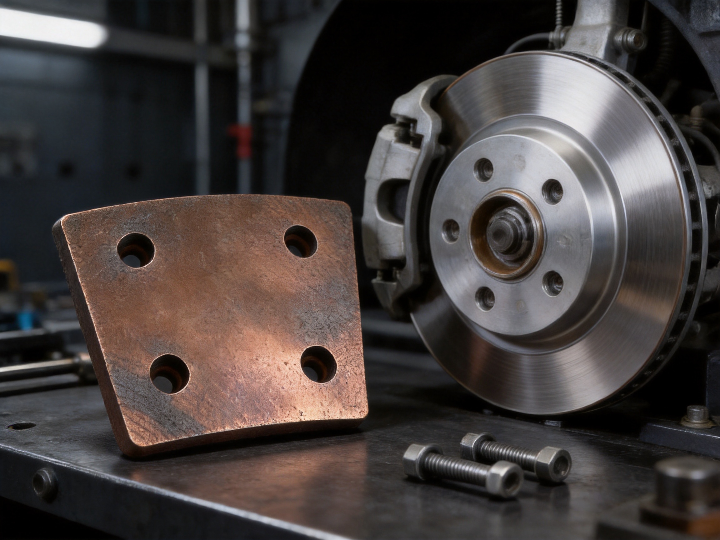
The four-hole mounting structure is designed to provide secure retention within a compatible industrial brake assembly. Holes distribute attachment points across the pad and help prevent movement caused by tangential braking forces. This is important because the pad is subjected not only to normal clamping pressure but also to shear forces generated as the rotor moves relative to the friction surface.
A properly designed hole pattern can reduce pad shifting, vibration, and uneven loading. It can also help maintain the intended relationship between the friction surface and the rotor throughout the service cycle. When the pad is securely positioned, the entire working face can participate more evenly in braking rather than relying on isolated contact areas.
The hole pattern must match the brake hardware accurately. Hole diameter, center-to-center distance, edge distance, positional tolerance, countersink or counterbore requirements, and fastener clearance should be confirmed from a current engineering drawing. Even a small mismatch can create assembly stress, loose attachment, restricted movement, or premature cracking around the mounting holes.
Hole edges require particular attention. Sharp edges or insufficient edge distance can concentrate stress during installation and operation. Controlled chamfers, radii, and surface finishing may be applied according to the customer’s assembly design. The manufacturing process can also be adapted to produce special mounting geometries for replacement parts or new equipment designs.
The mounting design should not be considered separately from the backing arrangement. A friction lining attached to a steel plate may experience different loads from a self-supporting pad. Bonding, riveting, bolting, or other attachment methods must be selected according to temperature, shear force, service environment, and maintenance requirements.
Dimensional Accuracy and Fitment Control
Dimensional control is essential for industrial brake pads because the component must fit within a defined caliper or brake housing while maintaining the correct clearance from the rotor. The nominal 79.5 × 62 × 7.3 mm dimensions provide a reference for the specified product, but the acceptable tolerance should be established by the customer’s drawing or equipment manufacturer.
Length and width influence the contact area and therefore the nominal contact pressure for a given clamping force. Thickness affects installation clearance, actuator travel, thermal capacity, and the point at which the pad should be replaced. Hole position influences attachment accuracy and the distribution of mechanical loads.
Dimensional inspection may be performed with calibrated gauges, coordinate measurement equipment, digital instruments, or dedicated fixtures. Measuring equipment should be selected according to the required tolerance and part geometry. Inspection records can provide traceability for production batches and help identify tool wear before it affects a significant number of parts.
Tooling stability is particularly important in powder metallurgy. Press dies and forming tools must maintain their geometry under repeated compaction cycles. Wear, galling, misalignment, or incorrect lubrication can cause variations in thickness, hole shape, density distribution, and edge condition.
Precision forming and secondary machining can be combined when the product requires tight tolerances or special features. The manufacturing route should be selected to balance dimensional accuracy, production efficiency, material integrity, and cost. Removing too much material after sintering may expose nonuniform regions or alter the intended friction surface, so machining allowances and finishing methods must be carefully planned.
Thermal Performance in Continuous and Emergency Braking
Brake energy is converted into heat at the contact interface. The ability to manage that heat is one of the main reasons industrial designers choose copper-based friction materials. High thermal conductivity helps distribute energy through the pad and into adjacent components, reducing the likelihood of severe local hot spots.
In a crane or hoist, the brake may control a suspended load and experience repeated holding or stopping cycles. In a wind turbine, the brake may be used for emergency stopping, rotor positioning, or maintenance locking. In a mining conveyor, the brake may need to stop a heavy moving belt or prevent rollback. These applications generate different heat profiles, but all require predictable performance under load.
The stated working temperature range of approximately -40°C to 600°C should be interpreted within the complete brake-system design. Actual allowable temperature depends on rotor material, ventilation, clamping force, speed, duty cycle, contact pressure, cooling conditions, and the formulation selected for the application.
Temperature should be evaluated at the friction interface rather than inferred only from ambient conditions. A cold outdoor environment does not guarantee a cold pad if the brake is operating continuously. Likewise, a high ambient temperature does not necessarily create excessive pad temperature if the system has effective heat dissipation and an appropriate duty cycle.
Thermal cycling can also influence service life. Repeated heating and cooling may produce expansion and contraction of the pad, backing plate, fasteners, and rotor. Material compatibility and controlled internal structure help reduce the risk of thermal cracking, delamination, or permanent distortion.
For new applications, testing should include the expected speed, pressure, temperature, stop frequency, and environmental conditions. Laboratory friction testing can provide useful comparative data, but field validation remains important because the complete brake assembly determines the actual thermal response.
Comparison with Conventional Friction Materials
Copper-based sintered brake pads offer several advantages over conventional organic or semi-metallic materials when used in heavy-duty environments. Organic materials may provide quiet operation and a low initial cost, but their binders can be more sensitive to high temperatures. Under severe repeated braking, binder degradation may contribute to fade, odor, smoke, or changes in mechanical strength.
Sintered materials do not depend on the same type of organic binder system. Their metallic matrix can maintain structural integrity at temperatures that would challenge many resin-based formulations. This makes them attractive for equipment that must brake frequently or dissipate large amounts of energy.
Sintered pads may also provide longer service life under high pressure and abrasive conditions. Their high density and metallic structure resist mechanical collapse and can maintain a more stable contact geometry. However, the correct formulation must be selected because a material optimized for high-temperature performance may not be ideal for a low-pressure, noise-sensitive application.
Compared with iron-based sintered pads, copper-based pads generally offer better thermal conductivity and can be more rotor-friendly. Iron-based materials may provide a higher friction coefficient and a higher temperature capability in certain formulations, making them suitable for selected presses, furnaces, or other high-temperature industrial systems. Copper-based pads are often preferred where heat transfer, wet-braking stability, and rotor preservation are especially important.
| Performance Factor | Copper-Based Sintered Pad | Iron-Based Sintered Pad | Organic or Resin-Based Pad |
|---|---|---|---|
| Thermal conductivity | High | Moderate | Generally lower |
| High-temperature stability | Very good in suitable formulations | Very good in suitable formulations | More dependent on binder temperature resistance |
| Typical friction range | Approximately 0.25–0.40 | Approximately 0.35–0.50 | Formulation dependent |
| Rotor aggressiveness | Generally low to moderate | Moderate to high | Generally moderate |
| Wet-braking consistency | Good when properly formulated | Application dependent | Application dependent |
| Resistance to repeated heavy braking | High | High | Moderate to low, depending on design |
| Typical industrial uses | Cranes, wind turbines, conveyors, mining equipment | High-temperature presses and severe-duty systems | Light-duty machinery and noise-sensitive applications |
No friction material is universally superior. The correct choice depends on pressure, speed, energy, temperature, rotor composition, environmental exposure, noise requirements, maintenance policy, and target service life. The advantage of the copper-based pad is its balanced performance for demanding industrial systems where thermal control and consistent braking are essential.
Manufacturing Process and Quality Assurance
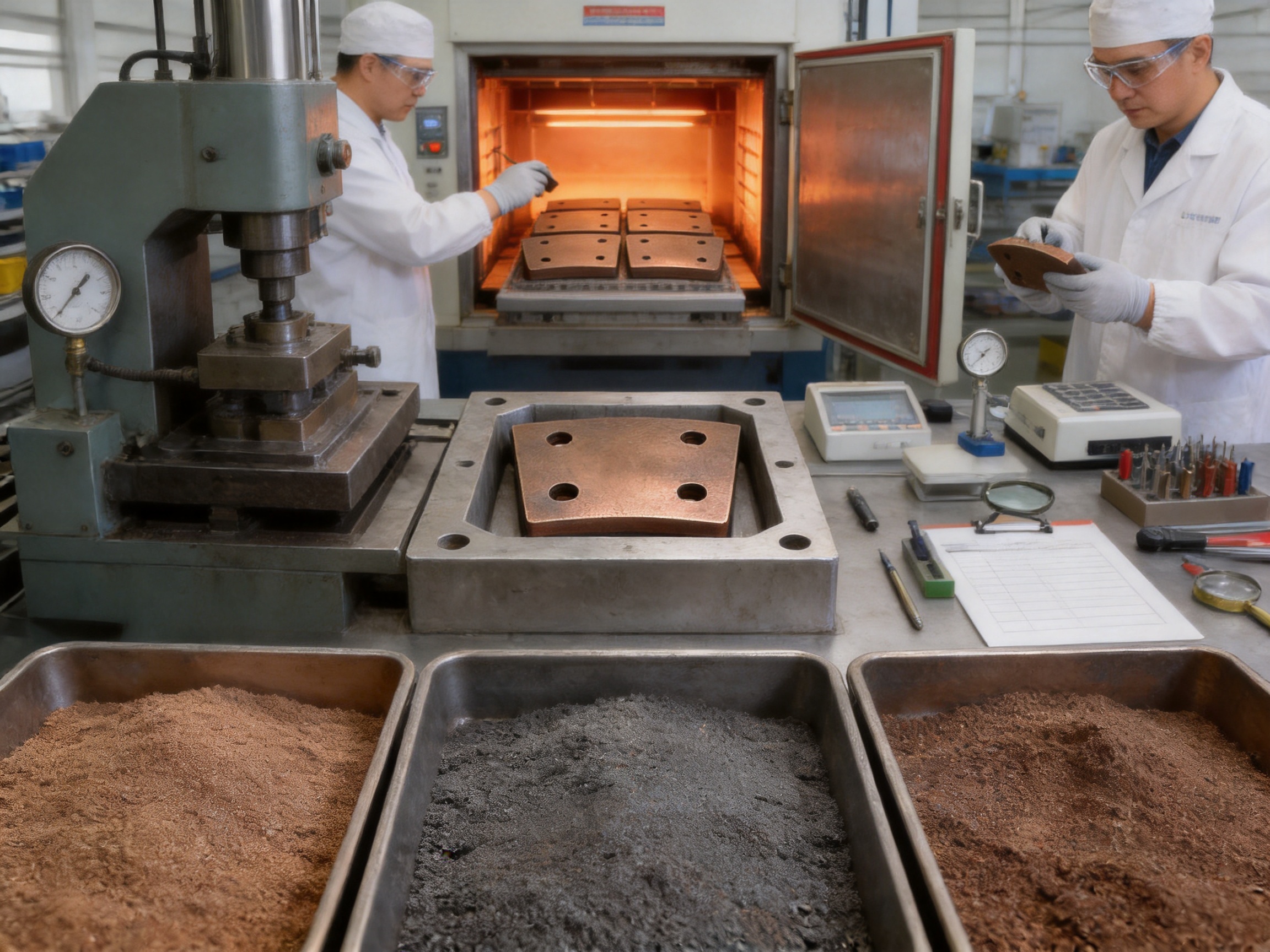
The manufacturing process begins with the preparation of approved raw materials. Copper powder, graphite, friction modifiers, reinforcing constituents, and other additives are selected according to the intended friction and mechanical properties. Material certificates, incoming inspection, storage conditions, and batch identification help maintain traceability.
Powder blending is performed to achieve uniform distribution. The formulation must be mixed sufficiently to prevent local variations while avoiding unnecessary particle damage or segregation. Process parameters may include batch size, mixing sequence, mixing time, equipment speed, and material loading order.
After mixing, the powder is transferred to a precision die. Consistent die filling is essential because uneven filling can produce density gradients in the compact. Such gradients may later become differences in strength, wear, shrinkage, or friction behavior.
Compaction forms the green part. Pressing force, dwell time, press speed, tooling alignment, and ejection behavior all influence the result. The objective is to achieve a compact with adequate green strength and a controlled density distribution without creating cracks or excessive internal stress.
Sintering is conducted in a high-temperature furnace under a controlled atmosphere. The furnace profile normally includes heating, temperature holding, and controlled cooling stages. During this cycle, particles bond through diffusion and the compact develops its final mechanical structure.
Atmosphere control is important because copper and other constituents can oxidize under unsuitable conditions. Oxide formation may reduce bonding quality, change friction behavior, or produce undesirable surface conditions. Furnace temperature uniformity and atmosphere monitoring support consistent results across the production load.
After sintering, parts may undergo sizing, calibration, hole finishing, deburring, surface treatment, or other secondary operations. These operations improve fitment and appearance while preserving the intended friction surface. Care must be taken not to contaminate the working face with oil, machining debris, or incompatible coatings.
Quality control can include dimensional inspection, density measurement, weight verification, visual examination, friction testing, wear testing, shear-strength evaluation, and metallographic analysis. Inspection criteria should be aligned with customer drawings, application requirements, and relevant technical standards.
A multi-stage quality system is stronger than relying only on final inspection. Process monitoring at raw-material preparation, mixing, pressing, sintering, and finishing stages makes it easier to identify the source of variation. This approach supports consistent production rather than simply sorting defective products after manufacturing.
The manufacturer operates an ISO 9001:2015 quality management system and an IATF 16949:2016 automotive quality management system. These systems support documented procedures, process control, traceability, corrective action, equipment management, and continual improvement. Certification does not replace product-specific testing, but it provides an organized framework for controlling manufacturing activities.
Advantages of the Manufacturing Partner
The manufacturing partner behind this product has operated since 2001 and focuses on powder metallurgy sintering and related precision machining. More than two decades of experience provide a practical foundation for handling complex powder formulations, tooling requirements, dimensional tolerances, and customer-specific industrial applications.
The company operates a modern production base of approximately 13,039 square meters and employs more than 150 skilled workers. Its equipment includes high-efficiency presses, high-temperature sintering furnaces, precision forming machines, and inspection equipment. This combination of personnel, facilities, and equipment supports both repeat production and customized OEM or ODM projects.
Customization is available for dimensions, density, friction characteristics, hole geometry, mounting configuration, and related design details. Customers can provide drawings, physical samples, or application parameters for evaluation. Engineering support can then be used to assess material selection, fitment, manufacturing feasibility, and inspection requirements.
For replacement parts, the ability to work from a sample or drawing is important because older industrial equipment may not have complete or current documentation. For new equipment, the manufacturer can support development from the design stage, helping coordinate the friction material with the rotor, caliper, backing plate, and operating duty cycle.
Quality assurance includes inspection for graphite segregation, cracks, dimensional deviation, and other defects. The stated product requirements emphasize uniform material distribution and defect-free construction, both of which are directly related to service reliability.
Technical support can include product selection, installation guidance, sample testing, performance verification, and after-sales communication. This support is valuable because friction performance depends on the complete system rather than the pad alone. Incorrect installation, rotor damage, excessive pressure, or unsuitable duty cycles can affect results even when the pad is manufactured correctly.
Competitive pricing and efficient order fulfillment are also important for industrial buyers. A brake pad that is technically suitable but difficult to obtain can create extended equipment downtime. Stable production capacity, clear communication, and batch traceability help customers plan maintenance and replacement schedules more effectively.
Application Scenarios
Heavy Engineering Machinery
Cranes, excavators, loaders, concrete pump trucks, and related machinery may require compact friction elements with high mechanical strength. Copper-based pads can support repeated braking and help dissipate heat generated by heavy moving components. The four-hole structure can provide stable attachment when the pad is exposed to strong tangential forces.
Metallurgical Equipment
Rolling mills, continuous casters, and steel plant machinery operate in environments where ambient heat, dust, vibration, and production continuity create severe demands. Reliable braking helps control large rotating assemblies and supports safe maintenance operations. Material selection should consider radiant heat, cooling conditions, and contamination from metal particles or scale.
Mining Machinery
Mine winches, conveyors, shearer loaders, and other mining equipment can experience high loads, abrasive dust, moisture, and irregular maintenance access. A durable sintered pad can help reduce replacement frequency while maintaining predictable braking during demanding cycles. The complete brake system should be protected from contamination and inspected regularly.
Wind Turbine Generators
Wind turbine yaw and pitch systems may use brakes for positioning, emergency stopping, or maintenance. The brake must function across changing weather conditions and temperature cycles. Copper-based friction material can offer useful thermal and wet-braking performance when matched to the rotor and caliper design.
Industrial Machine Tools and Elevators
Machine tools, elevators, and automated equipment often require accurate and repeatable braking. The pad must be dimensionally consistent and compatible with the available mounting space. Depending on the application, noise, vibration, stopping smoothness, and emergency holding capacity may be evaluated alongside wear resistance.
Marine and Offshore Equipment
Ship deck machinery and offshore platform equipment can be exposed to humidity, salt, vibration, and limited maintenance access. The friction material and associated hardware should be selected with corrosion protection and environmental sealing in mind. Proper storage and installation are particularly important for replacement pads used in marine environments.
Installation and Service Recommendations
Before installation, confirm that the replacement pad matches the required dimensions, hole pattern, thickness, friction direction, and backing arrangement. The rotor or mating surface should be inspected for grooves, cracks, excessive wear, contamination, and heat damage.
Mounting surfaces must be clean and free from oil, loose corrosion, and debris. Fasteners should be tightened according to the equipment manufacturer’s specifications. Over-tightening may damage the pad or distort the mounting structure, while insufficient tightening can permit movement and uneven loading.
The brake should be checked for correct alignment and free movement. The pad must contact the rotor evenly, without interference from surrounding hardware. If the assembly includes springs, pins, retainers, shims, or wear indicators, each component should be installed correctly.
A bedding-in procedure may be required. New pads and rotors may not initially have full-area contact. Controlled braking cycles allow the surfaces to conform gradually and establish a stable transfer film. Severe braking immediately after installation may cause localized hot spots or uneven material transfer.
During service, operators should monitor unusual noise, vibration, pulling, excessive dust, uneven wear, delayed release, or changes in stopping performance. These symptoms may indicate pad wear, rotor damage, caliper malfunction, contamination, incorrect adjustment, or another system-level issue.
Replacement intervals depend on load, speed, braking frequency, temperature, environment, rotor condition, and maintenance practice. The stated expectation that service life may be two to three times that of conventional friction materials should be verified under the customer’s actual operating conditions rather than treated as a universal guarantee.
Q&A: Common Questions About the Copper-Based Brake Pad
Q1: What is the main advantage of a copper-based sintered brake pad?
The principal advantage is the balance of thermal conductivity, mechanical strength, friction stability, and wear resistance. Copper helps transfer heat away from the friction interface, while the sintered structure supports repeated high-load braking. The actual performance depends on formulation, brake design, operating conditions, and correct installation.
Q2: What does the 6.2 g/cm³ density mean?
The density indicates the degree of consolidation and the controlled porosity of the pad. A properly controlled density supports structural strength, dimensional stability, and wear resistance. Density should be evaluated together with the friction formulation and application requirements because maximum density alone does not guarantee optimum braking performance.
Q3: Why is graphite segregation a concern?
Graphite contributes to lubrication and transfer-film formation. If graphite gathers in some areas and is absent from others, different regions of the pad may produce different friction and wear behavior. This can cause uneven contact, vibration, thermal hot spots, and inconsistent braking. Controlled powder preparation and inspection help prevent this problem.
Q4: What is the purpose of the four-hole design?
The four-hole design provides positive mechanical retention and helps distribute mounting forces. It reduces the likelihood of pad shifting under tangential braking loads and can improve stability during repeated operation. The hole diameter and position must match the brake assembly drawing.
Q5: Can the dimensions be customized?
Yes. Dimensions, thickness, hole pattern, density, friction characteristics, and other features can be customized for OEM or replacement applications. Customers should provide a drawing, sample, or complete technical specification so that fitment and manufacturing feasibility can be evaluated.
Q6: Is the 79.5 × 62 × 7.3 mm size suitable for every industrial brake?
No. The stated dimensions are the nominal specification for this product. Compatibility depends on the caliper, rotor, mounting hardware, contact area, clearance, clamping force, and operating duty cycle. The product should be verified against the equipment drawing before installation.
Q7: Can the pad operate in wet or outdoor conditions?
Copper-based formulations can provide good wet-braking stability when properly designed. However, water, mud, salt, oil, and abrasive contamination can affect any friction material. The brake assembly should be designed and maintained for its specific environmental conditions.
Q8: What inspections are performed before shipment?
Typical inspections include dimensional verification, weight or density measurement, visual examination, and checks for cracks, graphite segregation, and surface defects. Additional friction, wear, shear-strength, metallographic, or application-specific tests can be arranged according to customer requirements.
Q9: How should customers select between copper-based and iron-based sintered pads?
Copper-based pads are often preferred when heat dissipation, rotor friendliness, wet-braking stability, and balanced friction are important. Iron-based pads may be selected for certain higher-friction or high-temperature applications. The choice should be made using the complete duty cycle, rotor material, pressure, speed, temperature, and service objectives.
Q10: What information is needed for a customized quotation?
Useful information includes part drawings or samples, dimensions, hole locations, backing arrangement, rotor material, brake type, clamping force, operating speed, stop frequency, working temperature, environmental conditions, target friction coefficient, annual quantity, and required inspection documentation.
Q11: Can samples be supplied for testing?
Sample testing can be arranged for fitment checks and performance verification. Customers should define the intended test conditions and acceptance criteria so that the sample evaluation provides meaningful results.
Q12: How long can the brake pad last?
Service life depends on load, speed, pressure, braking frequency, temperature, rotor condition, contamination, and maintenance. Under suitable conditions, the product may provide substantially longer service than conventional friction materials, but field life must be confirmed through application testing and wear monitoring.
Recommended Customer Specification Checklist
When purchasing or developing a replacement brake pad, customers should identify the exact equipment model and brake assembly. A part number alone may be insufficient when machinery has been modified or supplied with different brake options.
The required dimensions should include length, width, thickness, hole diameter, hole spacing, edge distance, countersink details, and all relevant tolerances. The customer should also indicate whether the component is a complete pad, a lining, or a friction element intended for attachment to a separate backing plate.
Operating conditions should include maximum and normal speed, braking torque, clamping force, rotor diameter, rotor material, stop frequency, holding duration, ambient temperature, estimated interface temperature, and cooling method. Environmental information should cover water, oil, dust, salt, chemicals, vibration, and outdoor exposure.
Quality requirements should specify density tolerance, friction coefficient range, wear-rate target, shear strength, surface condition, allowable defects, inspection frequency, packaging, and documentation. Clear requirements reduce misunderstandings and make it easier to compare samples and production batches.
For critical safety applications, prototype testing should be completed before full-scale release. Testing may include dynamometer evaluation, thermal cycling, wet and dry braking, fade and recovery, wear measurement, rotor inspection, noise and vibration assessment, and endurance testing.
Conclusion
The high-density copper-based brake pad is designed as a reliable friction solution for demanding industrial braking systems. Its principal features include a copper-based sintered structure, nominal dimensions of 79.5 × 62 × 7.3 mm, a four-hole mounting configuration, 6.2 g/cm³ density, controlled friction behavior, high thermal conductivity, and resistance to wear under heavy-duty conditions.
Its performance advantage comes from the combination of material engineering and manufacturing control. Copper provides effective heat transfer, while powder metallurgy enables control over density, porosity, graphite distribution, and mechanical structure. Careful mixing, precision compaction, controlled-atmosphere sintering, secondary finishing, and multi-stage inspection work together to reduce defects and maintain batch consistency.
The product is suitable for cranes, mining machinery, metallurgical equipment, conveyors, wind turbines, elevators, machine tools, marine machinery, and other industrial systems that require dependable braking. The four-hole design supports stable mechanical retention, while customization capability allows the dimensions and friction properties to be adapted to specific brake assemblies.
For best results, selection should be based on the complete brake-system duty cycle rather than on pad dimensions alone. Rotor condition, clamping force, temperature, speed, environment, installation method, and maintenance practice all influence final performance. With accurate application data, appropriate testing, and controlled installation, this copper-based sintered friction material can help improve braking stability, reduce wear-related downtime, protect mating rotors, and lower total maintenance cost.
References
GB/T 5763-2018, Testing and Evaluation of Friction Performance for Automobile Brake Linings and Related Friction Materials.
GB/T 10419-2008, Test Methods and Technical Requirements for Shear Strength of Friction Materials.
GB/T 10421-2002, Test Methods for Wear Performance of Friction Materials.
GB/T 3399-1982, Thermal Conductivity Testing Methods for Relevant Industrial Materials.
ISO 9001:2015, Quality Management Systems—Requirements.
IATF 16949:2016, Quality Management System Requirements for Automotive Production and Relevant Service Parts Organizations.
ASM Handbook, Volume 7: Powder Metallurgy, ASM International.
Technical literature on sintered metallic friction materials, powder blending, compaction, controlled-atmosphere sintering, and industrial brake-system design.
Product: High-Density Copper-Based Brake Pad | 79.5×62×7.3mm | 4-Hole Industrial Brake Lining
Related products
-
-
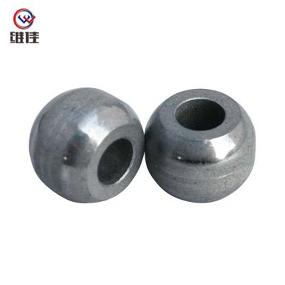
Product Description: High-precision powder metallurgy part (S14*7*10) made of iron material from Jiande Wefine, customized PM components with strict tolerance control.
See Details
Copyright © Jiande Welfine Technology Co., Ltd. All Rights Reserved. Privacy Custom Self-lubricating Sintered Bushing Manufacturers
